Products
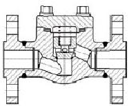
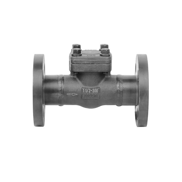
Welded flange swing check valve
Product Details


| Design and Manufacture | API602,ASME B16.34,BS5352 |
| Size | DN15-DN80 |
| Pressure | 150LB-2500LB |
| End Connection | Flanged end to ASME B16.5 |
| Inspection and Tes | API598 |
| Body Material | A105,LF2,F5,F11,F22,F304(L),F316(L),F304H,F316H,F51,F321,F91 F347,310S,Monel,Alloy 20,etc |
The Welded flangeswing check valve is characterized by large load changes and low opening and closing frequency.Once in the closed or open state,the service cycle is very long and does not require the rotation of moving parts.But once there is a switching requirement,it must be flexible.This requirement is more demanding than common mechanical movements.Since the check valve is qualitatively determined to be used for fast closing in most practical use,and the moment the check valve is closed,the medium flows in the reverse direction.As the valve flap is closed,the medium rapidly drops from the maximum backflow speed to zero,and the pressure rises rapidly,that is,the phenomenon of "water hammer"that may have a destructive effect on the pipeline system is generated.
Welded flangeswing check valve the purpose of this type of valve is to allow the medium to flow in only one direction and to prevent the flow in that direction.Usually this valve is automatic work,in one direction of the flow of fluid pressure under the action of the disc open;When the fluid flows in the opposite direction,the fluid pressure and the self-coincidence of the valve disc act on the valveseat,thus cutting off the flow.
Dimensions:
| Class | Size | Dimensions(mm | ||||
| NPS | DN | L | φd | H(open | φW | |
| 150LB(RF) | 1/2” | 15 | 108 | 10.5 | 155 | 100 |
| 3/4” | 20 | 117 | 13 | 157 | 100 | |
| 1” | 25 | 127 | 17.5 | 186 | 125 | |
| 1114" | 32 | 140 | 24 | 220 | 160 | |
| 11/2” | 40 | 165 | 29 | 246 | 160 | |
| 2" | 50 | 178 | 36.5 | 268 | 180 | |
| 300LB(RF) | 1/2” | 15 | 140 | 10.5 | 161 | 100 |
| 3/4” | 20 | 152 | 13 | 163 | 100 | |
| 1” | 25 | 165 | 17.5 | 200 | 125 | |
| 11/4” | 32 | 178 | 24 | 218 | 160 | |
| 11/2” | 40 | 190 | 29 | 253 | 160 | |
| 2” | 50 | 216 | 36.5 | 290 | 180 | |
| 600LB(RF) | 1/2” | 15 | 165 | 10.5 | 161 | 100 |
| 3/4” | 20 | 190 | 13 | 163 | 100 | |
| 1” | 25 | 216 | 17.5 | 200 | 125 | |
| 11/4” | 32 | 229 | 24 | 218 | 160 | |
| 11/2” | 40 | 241 | 29 | 253 | 160 | |
| 2” | 50 | 292 | 36.5 | 290 | 180 | |
| 900~1500LB(RF) | 1/2” | 15 | 216 | 10.5 | 200 | 125 |
| 314” | 20 | 229 | 13 | 200 | 125 | |
| 1” | 25 | 254 | 17.5 | 218 | 160 | |
| 11/4” | 32 | 279 | 24 | 253 | 160 | |
| 11/2” | 40 | 305 | 29 | 290 | 180 | |
| 2” | 50 | 368 | 36.5 | 335 | 250 | |
| 1500LB (RTJ) | 1/2” | 15 | 216 | 10.5 | 321 | 250 |
| 3/4” | 20 | 229 | 13 | 321 | 250 | |
| 1” | 25 | 254 | 17.5 | 321 | 250 | |
| 11/4” | 32 | 279 | 24 | 414 | 280 | |
| 11/2” | 40 | 305 | 29 | 414 | 280 | |
| 2” | 50 | 371 | 36.5 | 502 | 280 | |
| 2500LB(RTJ) | 1/2” | 15 | 264 | 10.5 | 321 | 160 |
| 3/4” | 20 | 273 | 13.5 | 321 | 160 | |
| 1” | 25 | 308 | 17.5 | 321 | 180 | |
| 11/4” | 32 | 352 | 24 | 408 | 200 | |
| 11/2” | 40 | 387 | 29 | 406 | 200 | |
| 2” | 50 | 454 | 36.5 | 495 | 249 | |


